DGFox 60 Evo
Adjusting has never been easier |
|
|
Caliper is the software tool designed to make it easy to calibrate your servo drive and motor via Microsoft Windows operating systems. An extremely intuitive graphical interface that speeds up and makes it even easier to access the entire set of features available on all HDT servo drives via a fast USB 2.0 port. Nothing could be simpler. With Caliper you will select the applications, save and load the data but you will also have a powerful professional oscilloscope for fine adjustment of the control loops, autophasing tools, instruments for automatic reduction of motor cogging, an observer filter to suppress vibrations , a Fieldbus analizer to check the state of fieldbus communications and many other functions to help you to adjust as good as possible your applications . |
|
Operating modes and technological functions |
|
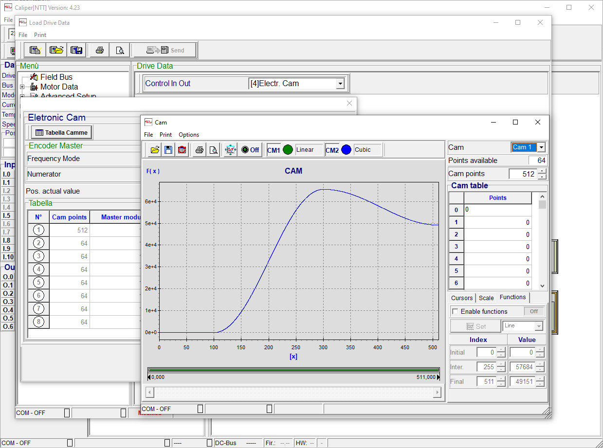
| Caliper allows you to activate and parameterize the operating modes and technological functions integrated in the HDT drives such as the "Speed", "Torque", "Speed and Torque limit" modes and the "Multi-positioner", "Electric Axis", " Electronic Cam "and" Pressure Control ". For each selected mode, the I/O are configured automatically by default but can be redefined at will by easy and intuitive menus, just as you can set the values of the points that form the electronic cam, or the reduction ratios between master and slave in the 'electric axis or the positions to be reached in the multi-positioner application and still many other functions to be discovered. Discover more..
|
|
Multi-positioner application |
|
|
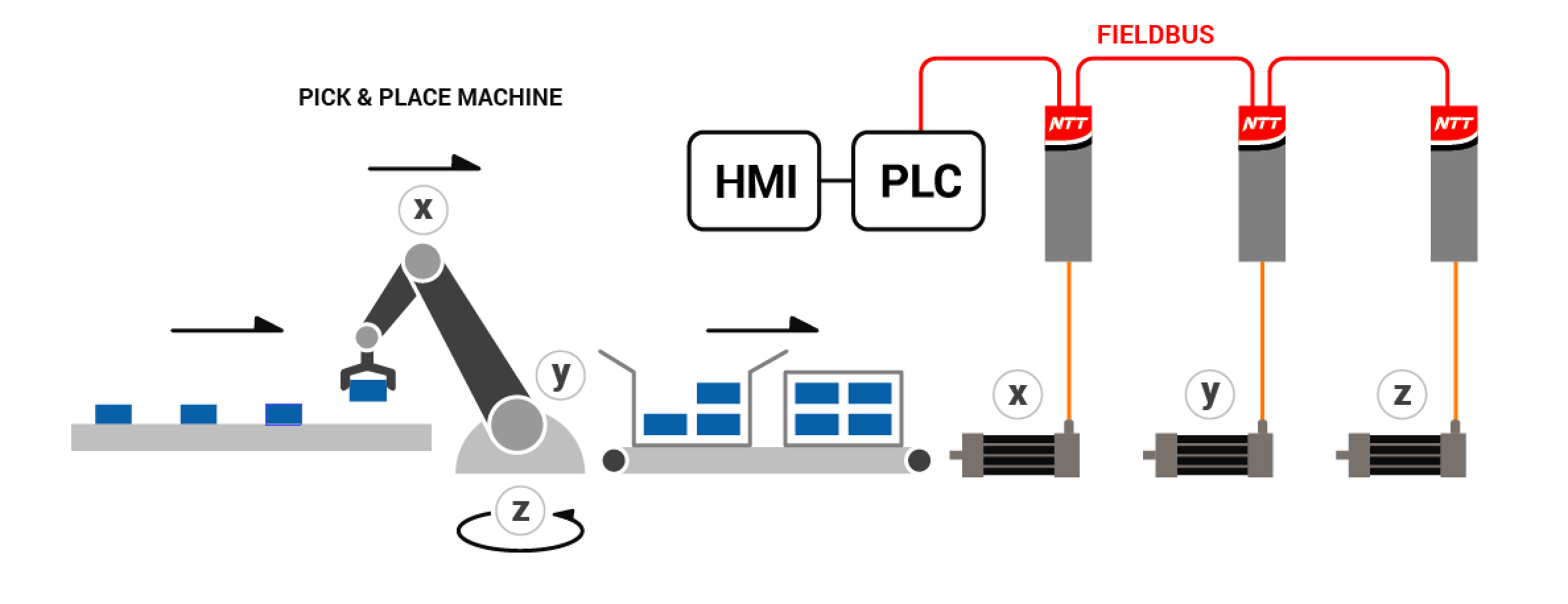
The TomCat Evo servo drive integrate a "multi-positioner" operating mode with 4 selectable modes. The positioner application generates a speed profile to reproduce a motion trajectory with controlled acceleration and jerk, allowing accurate positioning. The profile calculation is performed in real time allowing to modify on-the-fly the position target with time lower than 1 millisecond. This allows to manage in a fast way different motion profiles.The positioner includes a funcionality called "stop on input" that allows to perform a controlled position stop when a sensor signal is detected by a digital input of the drive during the execution of the trajectory. |
|
Single-target positioner. |
|
|
This mode can be activated both with digital/analogue input and with all field buses. The drive configured in this way allows to generate a trajectory profile only for a target defined as position target, with speed, acceleration, deceleration and jerk. The positions can be absolute or relative. Using the fieldbuses, all parameters can only be set on the fly by telegram, only the Modbus RTU allows to work with maximum flexibility using both modbus commands and digital / analog input commands. In a case a fieldbus is not available, position and speed can be set in analog mode via the respective input, while the other parameters can be set via Caliper software. |
|
Positioner with table of targets. |
|
|
This mode can be activated both with digital / analog inputs and with Modbus RTU and profiNet RT. The positioner allows to manage a maximum of 64 targets. As with the single target, for each target it is possible to set position, speed, acceleration, deceleration and jerk. The positions can be absolute or relative. The targets are wrote on a table on the drive or by Caliper or by the field bus. The targets can be executed individually or linked in different ways, allowing to generate more complex profiles. It is possible to cycle automatically the series of linked targets and to interpose a waiting time between one target and the other. |
|
Cyclic positioner. |
|
|
This mode is similar to the positioner with target from table, with the difference that the targets are strictly executed one after the other. The targets can be activated manually via I/O or via Modbus RTU. There is the option to make the sequence of set targets cyclical. |
|
Input-start" positioner. |
|
|
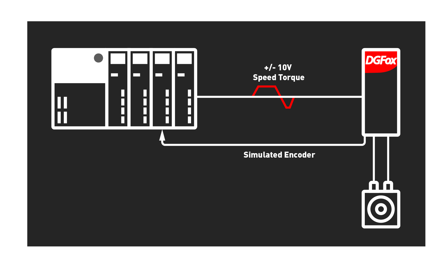
This mode allows to synchronize the starting of an axis with the reaching of the position of anoter axis, without the necessity to use a PLC. It is different from the previous one because the input that selects the target or the group of linked targets becomes the start command of the target itself. The "reached position" signal can be activated on each of the digital output of the drive. Therefore, connecting one of the output of reached target of a NTT servodrive with the input of another NTT servodrive, it allows the synchronized starting of the latter. This mode only works with digital/analog inputs and with the Modbus RTU field bus. |
|
Speed control and torque limit. |
|
|
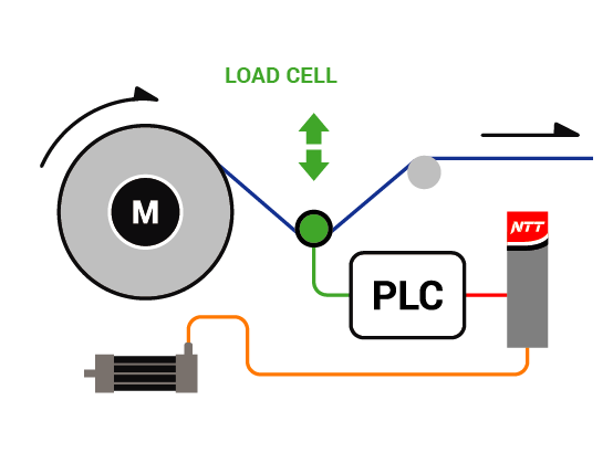
The speed control is a mode that allows to control the speed of the motor via a speed reference, managed by an analog input, a frequency input or fieldbus command.In I/O or Modbus mode it is possible to use an additional analog auxiliary speed reference or torque limit reference. Therefore it is possible to work in speed control mode, limiting the maximum torque by imposing a limit threshold. |
|
Torque control. |
|
| The torque control is a mode that allows to control the torque provided by the motor thanks to a torque reference managed by an analog input or a command sent via a ModBus, CanOpen, EtherCat or Profibus. The torque reference that is provided is in proportional to the rated torque of the motor. According to the type of reference you work with,in Caliper software it is possible to set different parameters, for example the full-scale for analog input, optimal PID controllers for the application and the desired digital I/O. | |
Pressure Control. |
|
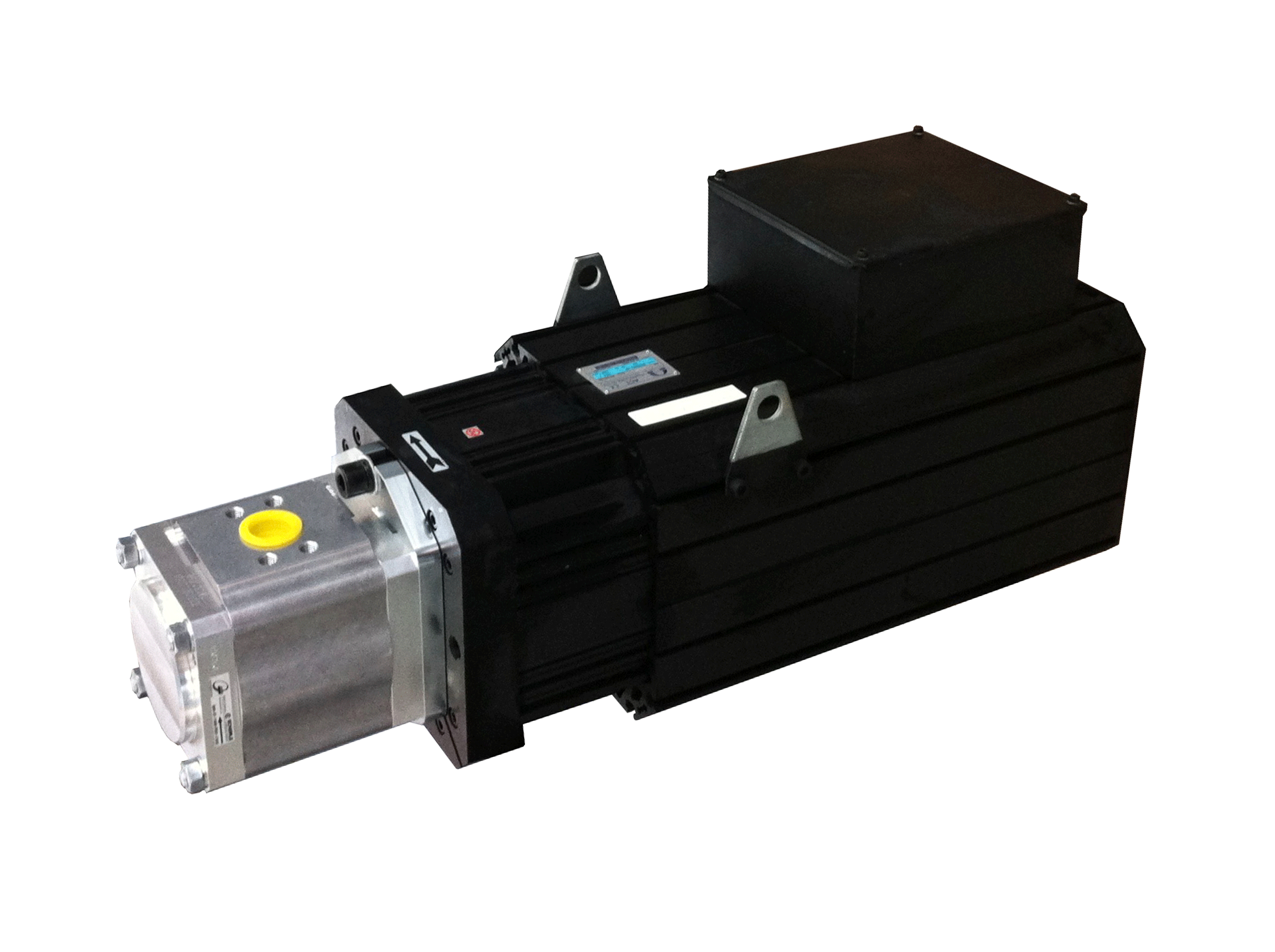
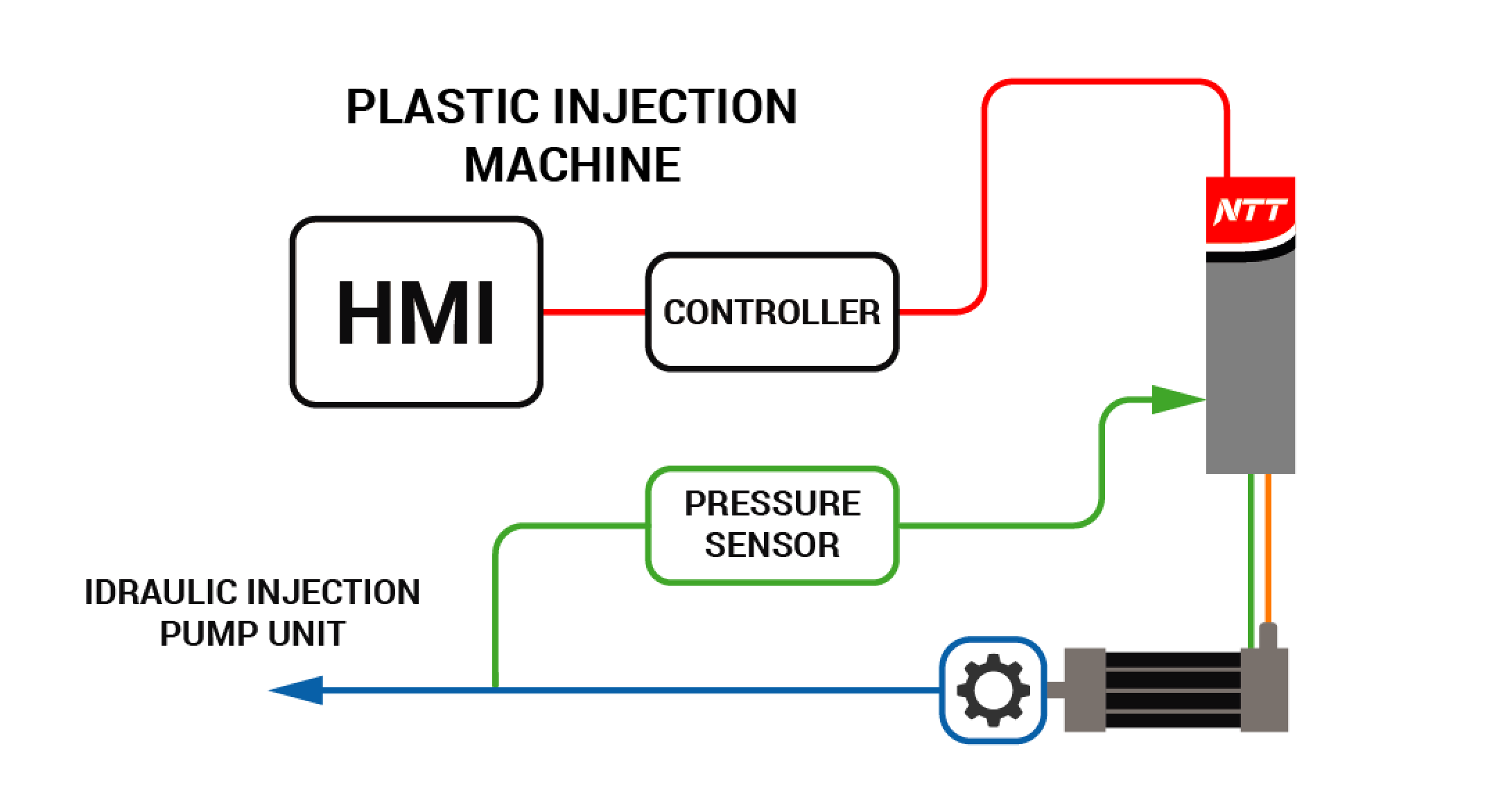
| The TomCat Evo servo drive integrates an operative mode called "pressure control", designed expressly for applications that use servo-pumps like in presses and plastic injection machines, which are applications that combine an idraulic system with an electrical regulation via servodrive and brushless motor. |
|
By activating this mode on NTT servodrives, three inputs are enabled. The first input for the speed reference signal is used to regolate the speed of a motor connected to a pump and so the respective flow. A second input is enabled to receive the pressure reference signal and a third input is enabled for the pressure transducer signal (pressure feedback). The two pressure signals are compared and the servodrive operated the control of speed to maintain the real pressure equal to that of the reference
The pairing of NTT with a brushless servomotor thanks to this applicative allows to replace a traditional system with pump and asynchronous motor, obtaining an incredible benefit in the system efficiency. Energy consumption is drastically reduced, oil temperature is reduced, idraulic system is simplified thanks to the elimination of the proportional valves and the pressure flow control is improved, thus also improve the product quality. Control system with minimal response times that allow a very accurate control with considerable improvement in the accuracy of moulding process. The drastic energy saving is due to the fact that NTT allows to stop the motor maintaining the system pressure with a near-zero power consumption, while in the traditional systems with asynchronous motor, the motor have to rotate at a fixed speed around 1500rpm to maintain the system pressure even if the application is not working.
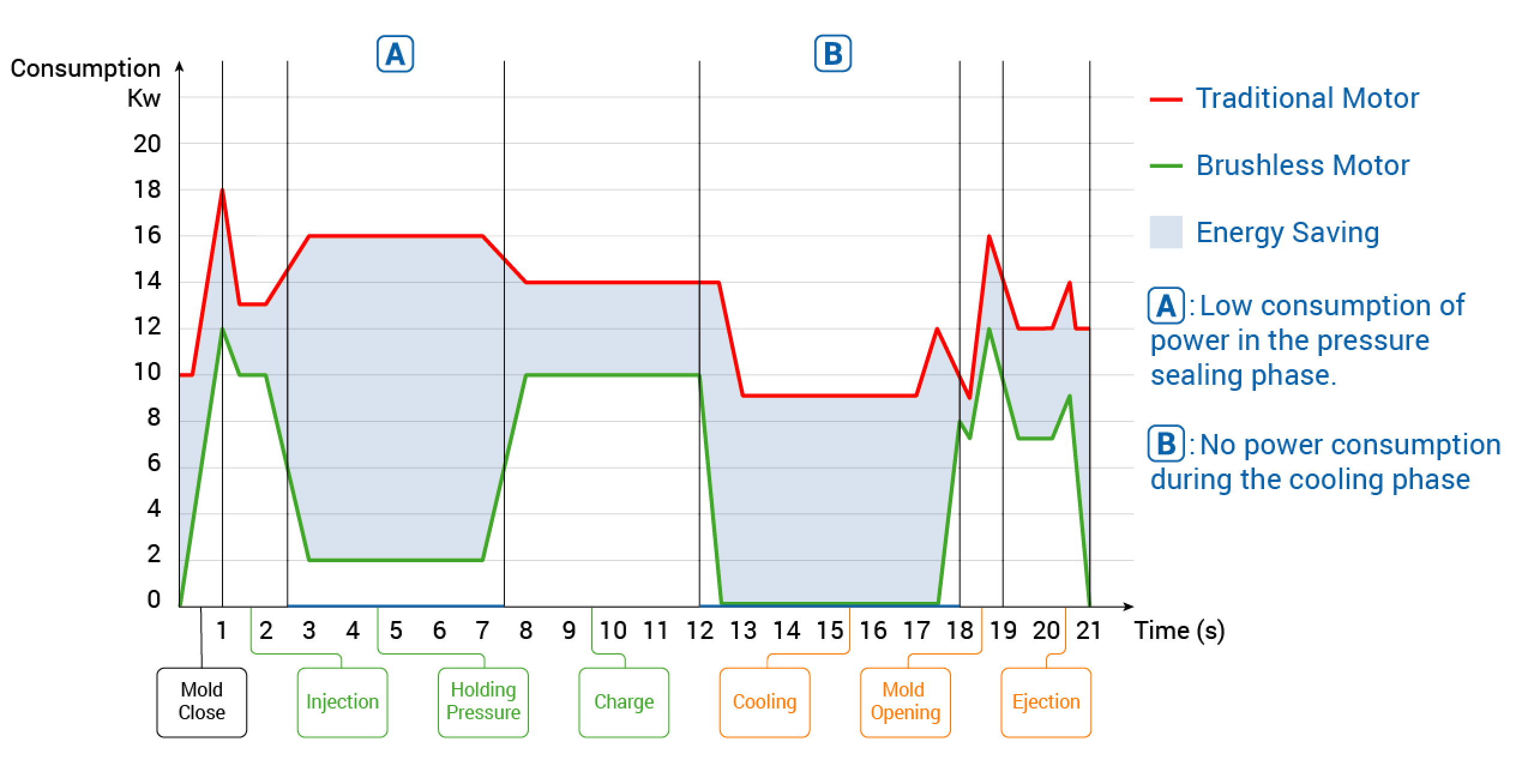
As a consequence, a pump equipped with NTT is managed with variable speed and allows the heating reduction compared to a circuit that constantly work at a fixed speed, even if only to maintain pressure. This improves the oil circulation in the system that is maintained at low temperatures, allowing the installation of radiators with small dimensions. The servodrive allows maximum repeatability in flux regulation granting a better quality of the product. Furthermore, among the motors, the brushless is the one with highest efficiency, with values around 95%. Not least, the system is much more silent and with lowe size.
Electronic axis. |
|
| The electric axis is a standard function of the NTT servodrive that allows to set an electronic transmission ratio between one or more motors, where a slave axis, or "follower", follow a master axis according to a preset ratio. This ratio is set in the slave drive and can be modified at will. The movement of the master is measured with an encoder which signal is sent to the input of the follower drive, that follows according the set ratio. The electronic axis replicates the mechanical transmission principle, in the same way done by a reducer, recirculating ball screw, a rack or a pulley and belt system. The trasmission with mechanical reduction allows to change speed, to increase torque and helps to match of inertia between motor and load. |
|
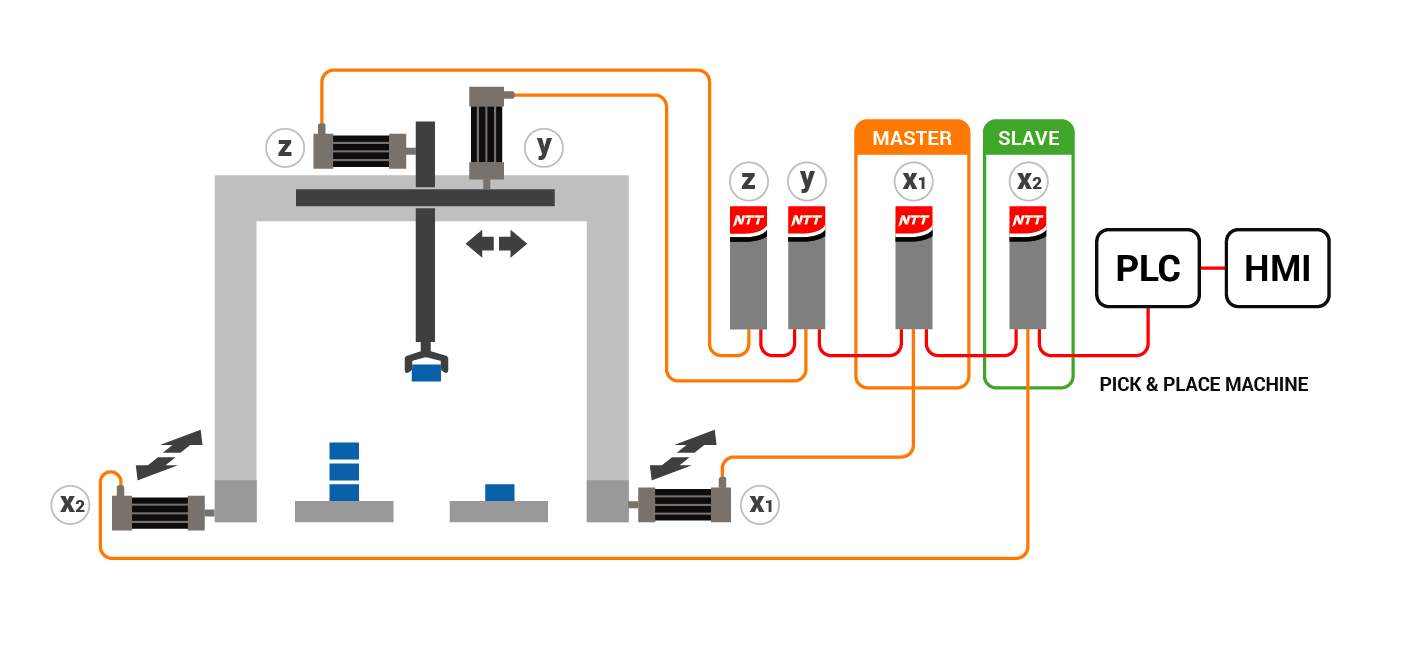
The electrical axis function, compared to mechanical reduction, only regulates the speed but with the advantage of allowing to change on will and to eliminate backlash and deterioration typical of mechanical systems. It is possible to connect different slave axes to a single master axis, with different electrial gear ratio. When managing the electrial axis, it is important to calibrate the parameters of slave axis, especially response times.
Electronic CAM control. |
|
| The electronic cam is an applicative that replicate the concept of mechanical cam. The mechanical cam is an element with irregular shape(tipically ovoid) fixed shaft of an axis and which moves another mechanical parts that follows and reproduces the profile. In the electronic cam, the mechanical regulation is replased with electronic. A cam profile is defined via X/Y table with a maximum of 576 interpolable points. Unlike the mechanical cam, where the cam profile is fixed to master axis, in the electronic cam the profile is inserted in the servodrive that drives the follower motor. |
|
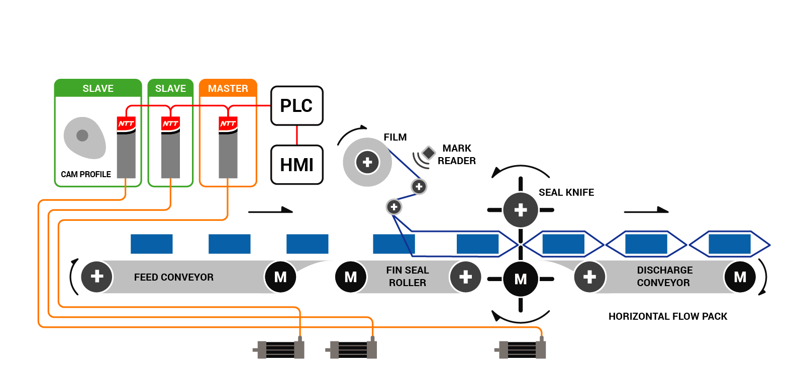
The "slave" axis receive the space reference of the "master" axis and replicate the profile described in the table of X/Y points, generating the resulting motion. The signal of the master axis can come from an esternal encoder or from the signal of a simulated encoder of a servo axis. The benefit of the electronic cam compared to the mechanical one is evident in the flexibility to manage more than one profile, to be able to modify the profile very easily in any moment and not least the reduction of mechanical backlash and the corresponding adjustments that follow.


